Design of asynchronous motors

Click on any of the sections below to expand its content.
We offer -> a complete set of technical documentation for a whole series of asynchronous motors with Premium Efficiency (IE3) for the power from 0.06kW and up to 400kW for the line voltage of 400V and the number of poles of 2, 4, 6 and 8 -> a complete set of technical documentation for a whole series of asynchronous motors with Super Premium Efficiency (IE4) for the power from 0.06kW and up to 400kW for the line voltage of 400V and the number of poles of 2, 4, 6 and 8 -> a complete set of technical documentation for a whole series of asynchronous motors with Ultra Premium Efficiency (IE5) for the power from 0.06kW and up to 400kW for the line voltage of 400V and the number of poles of 2, 4, 6 and 8 Please, find the detailed description in corresponding pages for IE3, IE4 and IE5 in the Products section above. Our technical documentation is enough to start off the production of a corresponding series.
Experimental verification of our design tools 1) on 2-pole asynchronous machines with all the standard output powers in the range from 0.09kW to 355kW; 2) on 4-pole asynchronous machines with all the standard output powers in the range from 0.06kW to 355kW; 3) on 6-pole asynchronous machines with all the standard output powers in the range from 0.18kW to 250kW; 4) on 8-pole asynchronous machines with all the standard output powers in the range from 0.25kW to 200kW;
Compliance of our motor design tools to standards We guarantee compliance of our motor designs with IEC/EN 60034-30-1: 2014. The starting torque in our motor designs is also in accordance with IEC.
Adjustability of our motor designs -> we are prepared to adjust our designs in order to comply with technical requests of the customer -> we are prepared to modify designs of specific components and spread these changes through the whole series;
Our design process
Video describing our design process
Input data for our design process Number of phases (e.g. 3) Nominal power (e.g. 15kW) Nominal line voltage (e.g. 380V) Power supply frequency (e.g. 50Hz) Synchronous rotation speed (e.g. 1500rpm) International protection (e.g. IP54) The developed design tools enable selection of a design strategy. This could be, for instance, a specific efficiency class. A starting torque ratio and a maximal torque ratio are assigned in accordance with IEC standards.
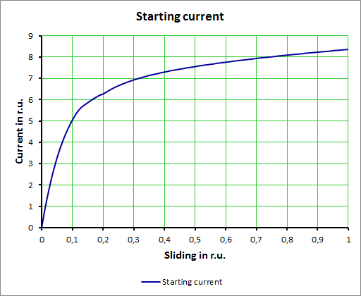
Calculation steps incorporated into our design tools 1) automatic determination of optimal dimensions of a motor for a defined height of the rotation axis, namely: the outer and the inner diameters of a stator, the air gap value, the active length of the stator, dimensions of the slots of the stator and of the rotor; 2) automatic determination of an optimal number of slots of the stator and of the rotor, an optimal number of turns in the stator winding, a cross-section of wire in the stator winding, as well as stator design and a stator winding diagram; 3) automatic electromagnetic simulation of the motor and estimation of the no-load current; 4) automatic determination of the parameters of the equivalent circuit of the motor, estimation of a power factor for the nominal load, calculation of performance characteristics of the motor; 5) automatic calculation of losses and the efficiency of the motor; 6) automatic calculation of the starting characteristics of the motor taking into account skin effects and saturation of the magnetic circuit of the motor; 7) automatic design and evaluation of the ventilation circuit of the motor; 8) automatic thermal calculation of the motor;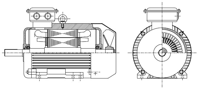
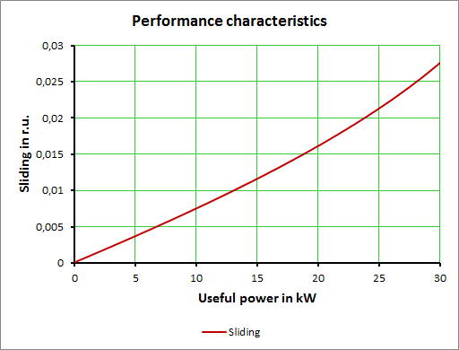
Performance characteristics In this section we present a typical set of performance characteristics from our design tools for one of our designs.


Optimization calculation Our design tools incorporate prior successful designs and are carefully tuned for reaching specified design targets. Our design routines and optimization strategies have been verified through years of experience and actual tests. However, if upon request of the customer design targets are modified, we can readjust our design tools accordingly. Additionally, we can introduce a limited optimization of a selected set of parameters of asynchronous motors.
Thermal analysis
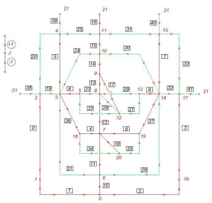
Basic scheme of our design process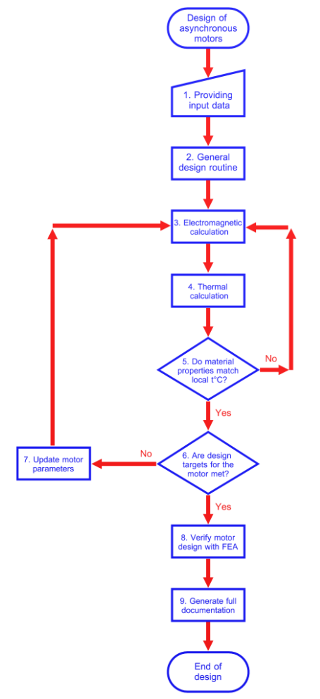
Capabilities of our design tools Our design software allows the development of asynchronous motors in accordance with any preselected target on efficiency: IE3 – Premium efficiency as specified in IEC/EN 60034-30-1: 2014 IE4 – Super Premium efficiency as specified in IEC/EN 60034-30-1: 2014 IE5 – perspective efficiency standard (20% lower losses compared to IE4)
We are using our tools for designing series of asynchronous motors in accordance with either IE3 or IE4 in a power range from 0.12 kW up to 400 kW for a line voltage of 400 V. We can develop asynchronous motors in accordance with any of the following implementations: IP54, IP55 or IP23. We can design asynchronous motors for a line voltage of over 1000 V and for powers of over 400 kW and up to 10 MW.
Validation of our design tools Our design tools show good correspondence with experiments. If we introduce geometry of an existing motor into the design tools, we get a good match with measured characteristics and observed temperatures. Below you will find a few calculations with our design tools for existing asynchronous machines and comparison with measurement data.
Validation example nr. 1: Induction motor 4A112M4
Technical data for 4A112M4
Value Catalogue data and measurements Our design software
Nominal useful power [kW] 5.5 5.5
Synchronous speed [rpm] 1500 1500
Number of poles 4 4
Nominal line voltage [V] 380 380
Frequency [Hz] 50 50
Number of phases 3 3
Connection of phases Y Y
Nominal torque [Nm] 36.322 36.309
Phase resistance at 20°C [Ohm] 0.995 0.987
Rotation speed at nominal load [rpm] 1446 1446.5
Nominal slip [%] 3.6 3.57
Nominal current [A] 11.498 11.016
Efficiency at 50% of load [%] 86.5 84.9
Efficiency at 75% of load [%] 86.5 85.7
Efficiency at 100% of load [%] 85.5 84.8
Power factor 0.85 0.85
Ratio of starting torque to nominal [r.u.] 2 2.009
Ratio of maximum torque to nominal [r.u.] 2.2 2.356
Ratio of starting current to nominal [r.u.] 7 6.07
Critical slip [r.u.] 25 20.2
No load current [A] 3.956
Flux density in air gap [T] 0.85 0.842
Losses in stator winding [W] 497.338
Losses in rotor cage [W] 208.893
Losses in steel [W] 191.402
Mechanical losses [W] 29.221
Additional losses at load [W] 32.307
Total losses [W] 932.749 958.161
Av. t° of stator winding at ambient t°= 40°C, °C 113.5 113
Validation example nr. 2: Induction motor 4A132M6 
Technical data for 4A132M6
Value Catalogue data and measurements Our design software
Nominal useful power [kW] 7.5 7.5
Synchronous speed [rpm] 1000 1000
Number of poles 6 6
Nominal line voltage [V] 380 380
Frequency [Hz] 50 50
Number of phases 3 3
Connection of phases Y Y
Nominal torque [Nm] 73.987 73.951
Phase resistance at 20°C [Ohm] 0.646 0.645
Rotation speed at nominal load [rpm] 968 968.5
Nominal slip [%] 3.2 3.15
Nominal current [A] 16.454 15.737
Efficiency at 50% of load [%] 84 83.2
Efficiency at 75% of load [%] 85 84.9
Efficiency at 100% of load [%] 85.5 84.7
Power factor 0.81 0.805
Ratio of starting torque to nominal [r.u.] 2 2.206
Ratio of maximum torque to nominal [r.u.] 2.5 2.8
Ratio of starting current to nominal [r.u.] 6 6.106
Critical slip [r.u.] 26 22.8
No load current [A] 7.499
Flux density in air gap [T] 0.87 0.872
Losses in stator winding [W] 611.545
Losses in rotor cage [W] 251.509
Losses in steel [W] 313.868
Mechanical losses [W] 29.933
Additional losses at load [W] 43.732
Total losses [W] 1271.93 1250.587
Av. t° of stator winding at ambient t°= 40°C, °C 105 111.4
Av. t° of housing at ambient t°= 40°C, °C 77 75.1
Verification with finite elements The purpose of this step is to confirm performance characteristics of the proposed motor design to the customer. Every motor design we deliver is verified with finite element tools in a fully automated fashion. Technical documentation We can design and develop all the components required for the motor and provide drawings and accompanying documentation. We can provide both assembly drawings and drawings of specific components. If the customer wishes to reuse some of his available parts, we could adjust our design accordingly.
Extra services on design of induction motors We perform mechanical analysis of shafts, housings, bearing shields. We can estimate mechanical forces acting on the stator winding during starting of the motor.